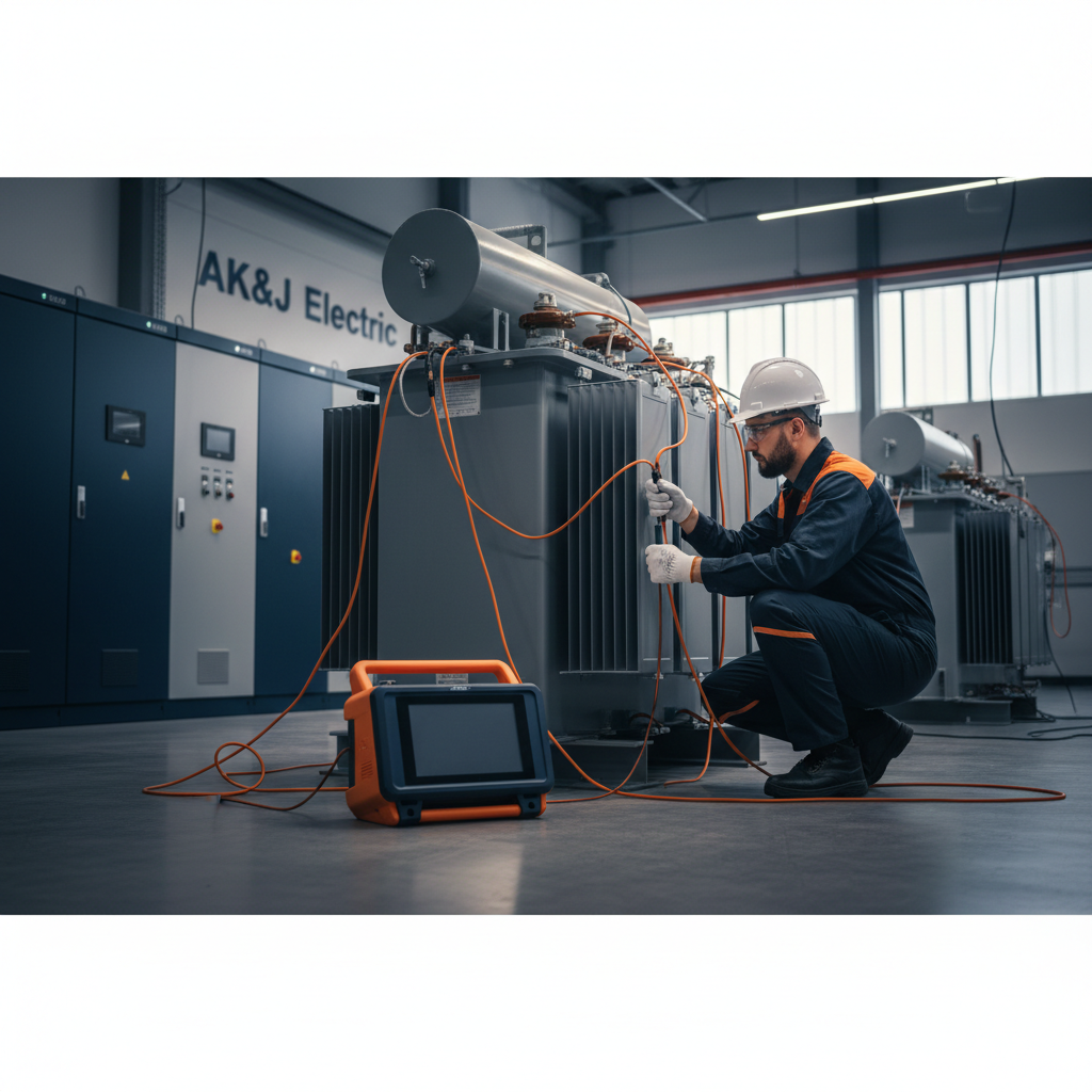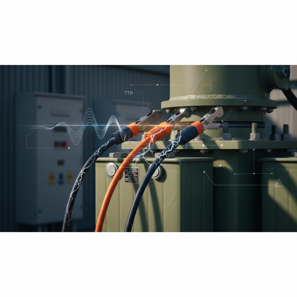
Transformers are the backbone of electrical distribution systems, but their reliability is not a given. Regular, thorough testing is essential to prevent costly failures, unplanned outages, and potential safety hazards. This guide focuses on three critical field tests: Transformer Turn-to-Turn Ratio (TTR), Winding Resistance, and Insulation Resistance, outlining practical, step-by-step workflows for facility managers and electrical contractors.
Workplace Safety First
Before initiating any transformer testing, strict adherence to safety protocols is paramount. NFPA 70E, "Standard for Electrical Safety in the Workplace," provides comprehensive guidelines for establishing an electrically safe work condition. This includes proper lockout/tagout procedures, verifying the absence of voltage, and using appropriate personal protective equipment (PPE).
Transformer Turn-to-Turn Ratio (TTR) Testing
The TTR test verifies the nameplate voltage ratio and identifies potential issues like shorted turns, open windings, or incorrect tap settings. Deviations from the expected ratio can indicate serious problems requiring immediate attention.
Why it Matters
Accurate voltage transformation is crucial for downstream equipment operation and system stability. A faulty TTR can lead to incorrect voltage levels, motor overheating, or insulation stress.
When to Test
- During commissioning of new transformers (NETA MTS Part 1 Table 100.1)
- After significant fault events or overloads
- Periodically as part of a routine maintenance program
- Before and after major repairs or relocation
Workflow
- De-energize and Isolate: Follow NFPA 70E procedures to establish an electrically safe work condition.
- Connect TTR Test Set: Connect the high-side leads of the test set to the transformer's high-voltage bushings (H1, H2, H3) and the low-side leads to the corresponding low-voltage bushings (X1, X2, X3). Ensure proper phasing.
- Apply Test Voltage: The TTR test set applies a safe, low AC voltage to one winding and measures the induced voltage in the other.
- Record Readings: Measure and record the voltage ratio for all phases (H-X, H-Y, H-Z, etc.) and all tap positions. Compare these readings to the transformer nameplate and design specifications.
- Analyze Results: NETA Acceptance Testing Specifications (NETA ATS) and Maintenance Testing Specifications (NETA MTS) typically allow a deviation of ±0.5% from the nameplate ratio. Larger deviations warrant further investigation.
Winding Resistance Testing
Winding resistance measurements detect issues like loose connections, broken strands, high-resistance contacts in tap changers, and localized overheating, which can lead to premature failure.
Why it Matters
Excessive winding resistance increases I²R losses, leading to higher operating temperatures and accelerated insulation degradation. It can also indicate manufacturing defects or damage due to through-faults.
When to Test
- During commissioning (NETA MTS Part 1 Table 100.1)
- After through-faults or sustained overloads
- Periodically during routine maintenance
- When investigating unusual operating temperatures
Workflow
- De-energize and Isolate: Ensure an electrically safe work condition per NFPA 70E.
- Connect Micro-Ohmmeter: Connect a DC micro-ohmmeter across each winding (e.g., H1-H2, H2-H3, H3-H1 for delta; H1-N, H2-N, H3-N for wye). Use Kelvin (four-wire) connections to eliminate lead resistance.
- Allow for Stabilization: Winding resistance is temperature-dependent. Allow the current to stabilize (minutes to hours depending on transformer size) to obtain accurate readings. Note the winding temperature.
- Record Readings: Measure and record the resistance for each winding at each tap position. Compare phase-to-phase readings and to factory test reports.
- Temperature Correction: Correct all resistance measurements to a common reference temperature (e.g., 20°C or 75°C) using the IEEE C57.12.90 standard formula for temperature correction. This allows for accurate comparison over time.
R_corrected = R_measured * ((T_ref + k) / (T_measured + k))- Where:
R_corrected= resistance at reference temperature;R_measured= measured resistance;T_ref= reference temperature (°C);T_measured= measured winding temperature (°C);k= constant (234.5 for copper, 225 for aluminum).
- Analyze Results: NETA MTS specifies that phase-to-phase resistance measurements should not vary by more than 2% for similar windings (e.g., three-phase delta) or 0.5% for windings with isolated phases. Significant deviations warrant investigation.
Insulation Resistance (Megger) Testing
Insulation resistance testing, often called