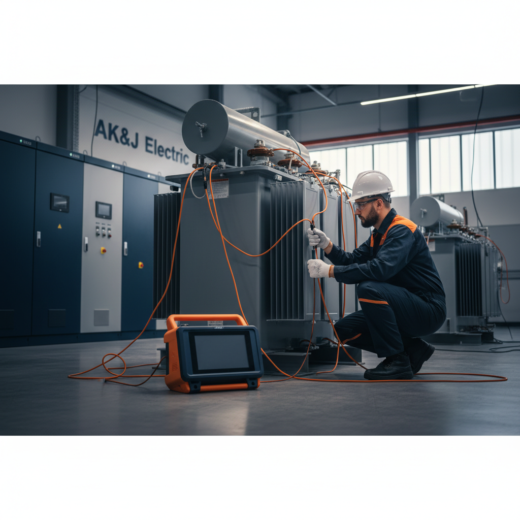
Transformers are critical assets in any electrical distribution system, essential for stepping voltages up or down to meet operational requirements. Their reliable performance is paramount for maintaining continuous power flow and preventing costly downtime. Regular testing is not just a best practice; it's a crucial component of a robust predictive maintenance program.
This article provides a practical, step-by-step field workflow for three fundamental transformer tests: Turn Ratio (TTR), Winding Resistance, and Insulation Resistance. Adhering to these procedures, as guided by industry standards, helps ensure the longevity and safe operation of your electrical infrastructure.
Understanding Transformer Tests
Each test provides unique insights into the health and integrity of a transformer. Together, they form a comprehensive picture of its operational readiness and highlight potential issues before they lead to catastrophic failure.
Turn Ratio Test (TTR)
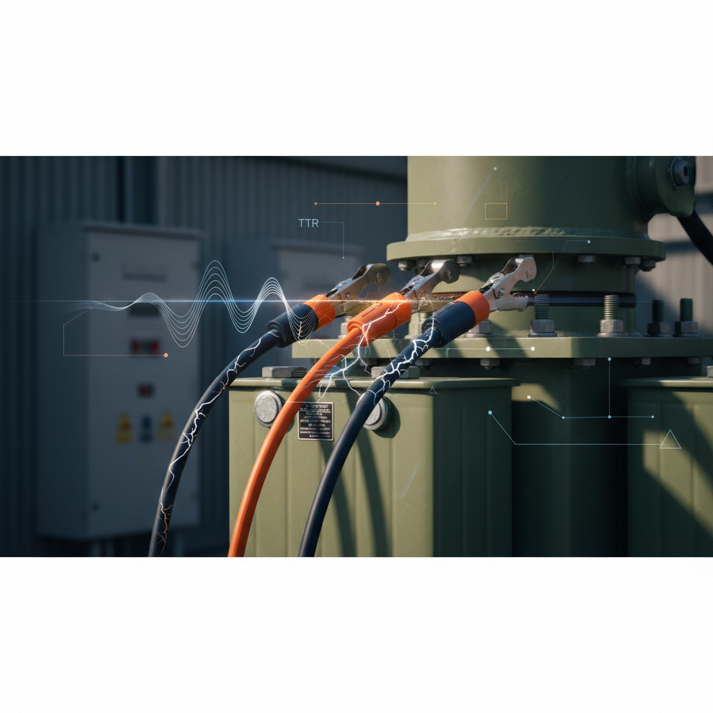
The Turn Ratio Test (TTR) verifies the transformer's turns ratio and polarity, ensuring it matches the nameplate specifications. Deviations can indicate winding damage, shorted turns, or incorrect tap settings.
Purpose:
- Confirm nameplate turns ratio.
- Detect shorted turns or open circuits.
- Verify correct tap changer operation.
- Identify incorrect winding connections.
Procedure:
- Safety First: Before commencing any work, ensure the transformer is de-energized, locked out/tagged out according to NFPA 70E, Standard for Electrical Safety in the Workplace, and properly grounded. Verify zero energy with an approved voltage detector.
- Equipment: Use a specialized TTR test set.
- Connections: Connect the high-voltage (H) leads of the test set to the primary windings and the low-voltage (X) leads to the secondary windings. Ensure proper polarity connections as per the test set instructions and transformer diagrams.
- Testing: Apply voltage to the primary side (typically a low AC voltage) and measure the induced voltage on the secondary side. The test set automatically calculates the turns ratio.
- Tap Changer: Perform the test on all tap positions (if applicable) to verify the ratio at each setting.
- Documentation: Record the measured ratios for all phases and taps, comparing them against nameplate values. NETA MTS (Maintenance Testing Specifications) typically recommends that measured ratios be within 0.5% of the nameplate value.
Winding Resistance Test
Winding resistance measurements are crucial for detecting abnormalities such as loose connections, broken strands, high-resistance joints, or localized overheating within the transformer windings.
Purpose:
- Detect open circuits or high resistance connections.
- Identify localized overheating or hot spots.
- Assess the condition of winding conductors and connections.
- Verify proper tap changer contact.
Procedure:
- Safety First: As with TTR, ensure the transformer is de-energized, locked out/tagged out per NFPA 70E, and grounded. Verify zero energy.
- Equipment: Use a low-resistance ohmmeter (micro-ohmmeter) capable of injecting a DC current and accurately measuring resistance in micro-ohms or milliohms.
- Connections: Connect the current and potential leads of the ohmmeter across the winding terminals. For delta-connected windings, individual phase windings must be isolated if possible, or calculations must account for the connection type.
- Stabilization: Allow sufficient time for the DC current to stabilize, especially for larger transformers with high inductance. This can take several minutes. The test set typically indicates when readings are stable.
- Readings: Take resistance readings for each winding (H1-H2, H2-H3, H3-H1 for delta primary; H1-H2, H2-H3, H3-H1, or H-N for wye primary, etc.) and for all tap positions.
- Temperature Correction: Winding resistance is highly temperature-dependent. Correct all readings to a common reference temperature (e.g., 20°C or 75°C) using the following formula (or use a test set that does this automatically):
R_corrected = R_measured * ((T_reference + k) / (T_measured + k))Wherekis 234.5 for copper and 225 for aluminum. - Documentation: Compare corrected readings between phases. NETA MTS often specifies that resistance values should not vary by more than 2% between phases for the same winding, nor vary significantly from previous test results.
Insulation Resistance Test (Megger Test)
Insulation resistance testing, often called a "Megger" test, assesses the integrity of the transformer's insulation system. It indicates the presence of moisture, contamination, or general insulation degradation.
Purpose:
- Evaluate the overall condition of the insulation.
- Detect moisture ingress or contamination.
- Identify insulation deterioration due to aging or thermal stress.
- Confirm insulation system integrity after maintenance or repair.
Procedure:
- Safety First: Ensure the transformer is de-energized, locked out/tagged out (NFPA 70E), and grounded. Verify zero energy. Important: Ensure all windings are discharged after the test, as capacitive stored energy can be hazardous.
- Equipment: Use a DC insulation resistance tester (Megohmmeter) capable of applying appropriate test voltages (e.g., 500V, 1000V, 2500V, 5000V), typically specified by NETA MTS or manufacturer guidelines. The NEC 2023, Article 110.4(A), requires equipment to be installed and maintained in accordance with manufacturer's instructions.
- Connections:
- HV to LV+Ground: Connect the positive lead to the high-voltage windings and the negative lead to the low-voltage windings and the transformer tank/ground simultaneously. This measures the resistance between HV and LV windings, and between HV and ground.
- LV to HV+Ground: Connect the positive lead to the low-voltage windings and the negative lead to the high-voltage windings and the transformer tank/ground. This measures the resistance between LV and HV windings, and between LV and ground.
- HV to Ground (LV Floating): Connect positive to HV, negative to ground, with LV floating.
- LV to Ground (HV Floating): Connect positive to LV, negative to ground, with HV floating.
- Test Application: Apply the specified DC test voltage for a duration (e.g., 1 minute for a spot reading, or 10 minutes for a Polarization Index (PI) test). For PI, record readings at 1 minute and 10 minutes.
- Readings & Interpretation: Record the resistance values in Megohms. The Polarization Index is the 10-minute reading divided by the 1-minute reading. A higher PI typically indicates better insulation condition. Minimum acceptable values are specified by standards like NETA MTS, often in the range of hundreds of Megohms to Gigaohms, and a PI typically above 2.0 for good insulation.
- Temperature Correction: Insulation resistance decreases with increasing temperature. Correct readings to a reference temperature (e.g., 20°C) if a direct temperature correlation chart is available for the insulation material, or trend data over time.
- Documentation: Record all readings, test voltage, duration, ambient temperature, and humidity.
Summary of Key Transformer Tests
| Test | What it Detects | Primary Standard Guide |
|---|---|---|
| Turn Ratio (TTR) | Shorted turns, incorrect tap setting, polarity | NETA MTS |
| Winding Resistance | Loose connections, broken strands, hot spots | NETA MTS |
| Insulation Resistance | Moisture, contamination, insulation aging | NETA MTS, IEEE C57.12.90 |
Maintenance and Trending
Consistent testing and meticulous record-keeping are paramount. Trending test results over time provides invaluable data, allowing facility managers and engineers to identify subtle degradation patterns that might not be apparent from a single test. This proactive approach enables scheduled maintenance or replacement, preventing unforeseen outages.
Adherence to a regular testing schedule, such as that outlined in NETA MTS, ensures that critical equipment remains in optimal condition, compliant with safety standards like NFPA 70E, and continues to operate efficiently within the parameters set by codes like NEC 2023.
Bottom Line
Thorough, regularly scheduled transformer testing using methods like TTR, winding resistance, and insulation resistance is fundamental to electrical system reliability and safety. These tests provide actionable data that allows for early detection of potential failures, ensuring compliance with industry standards and extending the operational life of vital assets. Investing in comprehensive testing and maintenance protects your equipment and prevents costly unplanned downtime. AK&J Electric provides expert transformer testing, commissioning, and maintenance services, ensuring your critical assets operate at peak performance.