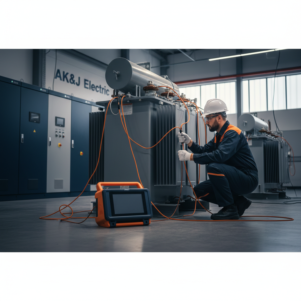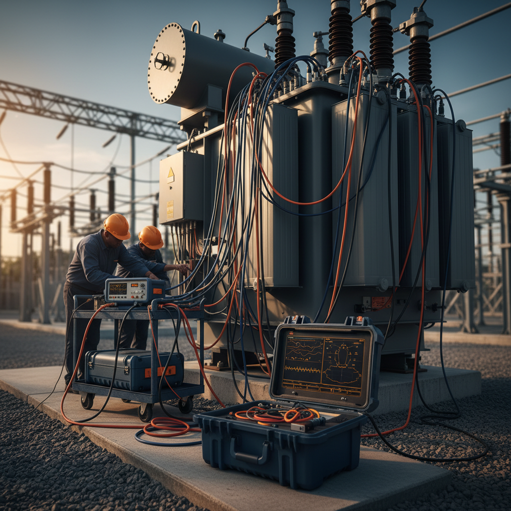
Transformers are critical assets in any electrical distribution system, and their reliable operation is paramount for continuous power delivery. Regular field testing is essential to assess their condition, identify potential issues, and ensure they meet design specifications after installation or maintenance. This article focuses on three fundamental transformer field tests: Turns Ratio (TTR), Winding Resistance, and Insulation Resistance, outlining a practical, standards-compliant workflow.
Safety First
Before initiating any testing, always prioritize safety. This includes de-energizing the transformer, isolating it from all power sources, and applying proper lockout/tagout procedures as stipulated by NFPA 70E, Standard for Electrical Safety in the Workplace. Verify zero energy using an adequately rated and tested voltage detector. Grounding of all transformer terminals is critical before physical work or testing begins.
Transformer Turns Ratio (TTR) Test
The TTR test verifies the transformer's voltage ratio and polarity. It compares the number of turns in the primary winding to the number of turns in the secondary winding, ensuring it matches the nameplate data and design specifications. Deviations can indicate winding damage, shorted turns, or incorrect tap settings.
Why it's Important
A correct turns ratio is fundamental for proper voltage transformation and system coordination. An incorrect ratio can lead to over- or under-voltages, affecting connected equipment and potentially causing system instability. NETA MTS (Maintenance Testing Specifications) typically recommends TTR testing for acceptance and maintenance.
Field Workflow for TTR Testing
- Preparation: Ensure the transformer is de-energized, isolated, and grounded. Identify all primary and secondary terminals, including tap changers.
- Equipment Setup: Connect a three-phase TTR test set to the transformer terminals. Generally, the high-voltage (H1, H2, H3) terminals are connected to the test set's high-voltage leads, and the low-voltage (X1, X2, X3) terminals to the low-voltage leads.
- Test Procedure: Apply a low AC voltage (typically 8VAC to 250VAC, depending on the test set and transformer rating) to one winding, and the test set measures the induced voltage on the other winding. The ratio is then calculated.
- Tap Changer Operation: If the transformer has a tap changer, perform the TTR test at all tap positions (e.g., NETA MTS-2023, Table 100.1, indicates testing at each tap position).
- Record and Analyze: Record the turns ratio for each phase and tap position. Compare results to the transformer nameplate and design specifications. A deviation of more than 0.5% (IEEE C57.12.90, NETA ATS-2023) from the nameplate or adjacent phases often warrants further investigation.
Winding Resistance Test
The winding resistance test measures the DC resistance of each winding. This test is crucial for detecting abnormalities such as loose connections, broken strands, high-resistance contacts in tap changers, or winding damage. It also provides data for calculating I²R losses.
Why it's Important
Uniform winding resistance across phases (for a three-phase transformer) is expected. Significant differences can indicate serious internal damage or degradation that could lead to hot spots and premature failure. NETA MTS specifies winding resistance tests for acceptance and routine maintenance.
Field Workflow for Winding Resistance Testing
-
Preparation: As with TTR, ensure the transformer is de-energized, isolated, and grounded. The transformer core should be fully saturated for accurate readings; allow sufficient time after de-energization (minutes to hours, depending on transformer size).
-
Equipment Setup: Use a low-resistance ohmmeter (micro-ohmmeter or milli-ohmmeter capable of injecting several amps of DC current). Connect the test leads to the appropriate winding terminals. For delta windings, a common approach is to measure resistance across terminals and then calculate the per-phase resistance. For wye windings, measure from terminal to neutral.
-
Test Procedure: Inject a stable DC current into the winding and measure the voltage drop. The instrument calculates resistance using Ohm's Law (R=V/I). Allow readings to stabilize, especially on large transformers, to account for winding inductance.
-
Temperature Correction: Winding resistance is temperature-dependent. Correct all measured resistances to a common reference temperature (e.g., 20°C or 75°C, as per IEEE Std C57.12.00 or C57.12.90) for accurate comparison over time. Use the following formula:
R_corrected = R_measured * [(T_reference + k) / (T_measured + k)]Where
kis 234.5 for copper and 225 for aluminum windings. -
Record and Analyze: Record the corrected resistance values for all windings and tap positions. Compare phase-to-phase values (they should be within 1–2% of each other, as per NETA ATS-2023) and compare to factory test data or previous maintenance records.
Insulation Resistance (Megger) Test
The insulation resistance test evaluates the integrity of the transformer's insulation system. It measures the resistance to ground or between windings, indicating contamination, moisture ingress, or insulation degradation.
Why it's Important
Healthy insulation prevents current leakage and breakdowns. A low insulation resistance reading suggests a compromised insulation system, increasing the risk of flashover and equipment failure. This test is a fundamental diagnostic tool, often a prerequisite before energizing a transformer, as outlined in NFPA 70 "National Electrical Code" Article 450 (Transformers) and NETA MTS.
Field Workflow for Insulation Resistance Testing
-
Safety: Confirm the transformer is de-energized, isolated, and grounded. Remove all temporary grounds before testing. Short-circuit all windings to ground for a period (e.g., 5-10 minutes) before the test to discharge any capacitive charge and ensure safety.
-
Equipment Setup: Use an insulation resistance tester (megohmmeter or "megger") with appropriate voltage ratings (e.g., 500V, 1000V, 2500V, 5000V DC, depending on transformer voltage class). Connect the "Line" terminal of the megger to the winding under test and the "Ground" terminal to the transformer tank/ground system.
-
Test Connections (Typical):
- HV to LV & Ground: Measures insulation between primary winding and secondary winding/tank.
- LV to HV & Ground: Measures insulation between secondary winding and primary winding/tank.
- HV to Ground (with LV grounded): Measures insulation of HV winding to ground.
- LV to Ground (with HV grounded): Measures insulation of LV winding to ground.
Note: Always refer to the specific test procedures recommended by the transformer manufacturer and NETA MTS.
-
Test Procedure: Apply the DC test voltage for a specified duration (e.g., 1 minute for spot readings, 10 minutes for a Polarization Index (PI) test). Readings should generally increase over time if the insulation is dry and clean.
-
Record and Analyze: Record the resistance values at 1 minute and, if performing a PI test, at 10 minutes. Calculate the PI (10-minute reading / 1-minute reading). A PI value significantly above 2 typically indicates dry and good insulation condition (NETA MTS-2023, Table 100.18). Compare results to baseline data, IEEE C57-series standards, and manufacturer recommendations. Low readings, particularly with low PI, suggest moisture or contamination and warrant further investigation or drying out.
Insulation Resistance Test Values (General Guide for Oil-Filled Transformers)
| Test Voltage (DC) | Minimum Resistance (MΩ) | Condition |
|---|---|---|
| 500V | ≥ 100 | Good |
| 1000V | ≥ 200 | Good |
| 2500V | ≥ 500 | Good |
| 5000V | ≥ 1000 | Good |
Note: These are general guidelines; always consult manufacturer specifications and industry standards like NETA MTS for specific acceptance criteria.
Bottom Line
Comprehensive transformer field testing involving TTR, winding resistance, and insulation resistance is indispensable for assessing asset health, ensuring operational reliability, and identifying potential failure points before they lead to costly outages. Adhering to established industry standards like NETA, IEEE, and NFPA is critical for safe and effective testing. AK&J Electric provides expert transformer testing, commissioning, and diagnostic services to help facility managers maintain peak electrical system performance and extend asset life.