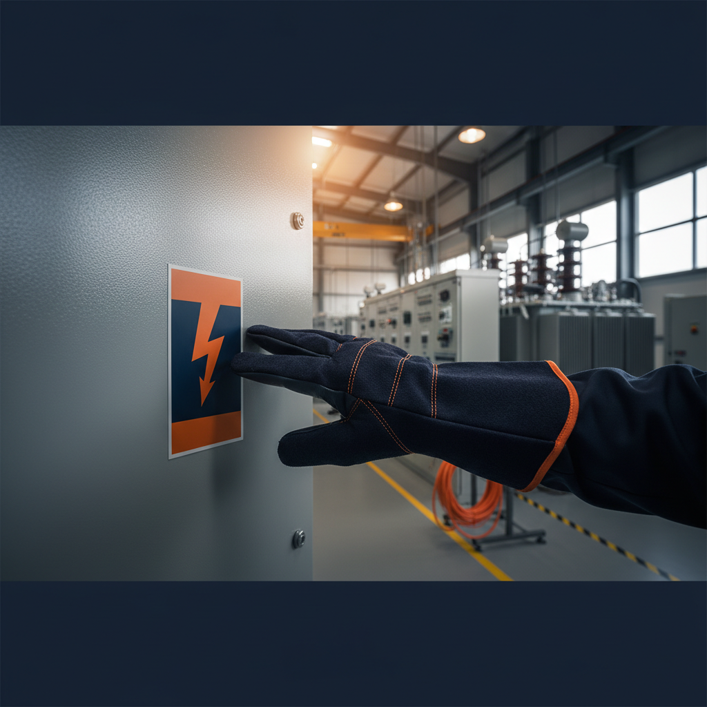
Navigating the complexities of an arc flash study report can feel daunting, even for experienced facility managers and plant engineers. These detailed documents are essential for ensuring workplace safety and compliance with critical standards, but their technical nature often leaves stakeholders unsure how to translate the data into actionable safety measures. This article aims to demystify these reports, highlighting the key information you need to extract to protect your personnel and facility.
Why Arc Flash Studies Matter
An arc flash study, often conducted by qualified electrical engineers, is a critical component of an electrical safety program. Its primary purpose is to determine the potential arc flash hazard at various points within an electrical distribution system. This involves calculating incident energy levels, identifying arc flash boundaries, and specifying appropriate personal protective equipment (PPE) for workers. Without a current and accurate arc flash study, facilities risk non-compliance with standards like NFPA 70E and exposing personnel to severe, even fatal, electrical hazards.
Key Components of an Arc Flash Study Report
While reports vary in format, several core sections are common and vital for understanding your facility's risk profile.
1. Executive Summary
This section provides a high-level overview of the study's findings, recommendations, and any identified deficiencies. It's an excellent starting point to grasp the overall scope and critical issues without diving into granular details immediately.
2. System Description and Assumptions
Here, the report outlines the electrical system studied, including one-line diagrams, protective device coordination, and any assumptions made during the analysis (e.g., utility contribution, motor contributions). Understanding these assumptions helps contextualize the calculations.
3. Incident Energy and Arc Flash Boundary Calculations
This is the heart of the report. It details the methodology used for calculations, typically adhering to IEEE 1584 standards. For each analyzed point in the system, you'll find:
- Incident Energy (IE): Measured in cal/cm², this is the amount of thermal energy that would be impressed on a surface at a specific distance from the arc source. Higher values indicate greater hazard.
- Arc Flash Boundary (AFB): This is the distance from a potential arc source within which a person could receive a second-degree burn (1.2 cal/cm²) if exposed to an arc flash. Proper PPE is mandatory within this boundary.
4. Shock Hazard Analysis
Beyond arc flash, the report also addresses shock hazards. Key terms here include:
- Limited Approach Boundary: The closest an unqualified person can approach exposed energized electrical conductors or circuit parts.
- Restricted Approach Boundary: The distance from exposed energized conductors or circuit parts within which there is an increased risk of shock due to arcing over and inadvertent movement. Only qualified persons with appropriate PPE and tools are permitted within this boundary.
These boundaries are defined by NFPA 70E, Standard for Electrical Safety in the Workplace.
5. Personal Protective Equipment (PPE) Recommendations
Based on the calculated incident energy levels, the report will specify the required PPE for different locations. This includes arc-rated clothing (e.g., shirts, pants, coveralls), face shields, gloves, and other protective gear. PPE is often categorized by its Arc Thermal Performance Value (ATPV) or Energy Breakopen Threshold (EBT), measured in cal/cm², which must meet or exceed the calculated incident energy.
Decoding Arc Flash Labels
The most visible outcome of an arc flash study is the application of arc flash labels to electrical equipment. These labels, typically affixed to panelboards, motor control centers, and switchgear, serve as a quick reference for workers. While designs vary, common elements include:
- Nominal System Voltage: e.g., 480V, 208V.
- Incident Energy (cal/cm²): At a specified working distance (e.g., 18 inches).
- Arc Flash Boundary (AFB): In feet or inches.
- Required PPE: Often listed by hazard risk category (HRC) or simply the minimum ATPV/EBT rating.
- Limited and Restricted Approach Boundaries.
- Date of Study/Revision: Essential for ensuring the information is current.
Example Arc Flash Label Information
| Item | Value |
|---|---|
| Equipment | Main Distribution Panel (MDP-1) |
| Nominal Voltage | 480V |
| Incident Energy | 8.5 cal/cm² @ 18" working distance |
| Arc Flash Boundary | 5.0 ft |
| Limited Approach | 3.5 ft |
| Restricted Approach | 1.0 ft |
| Required PPE | Arc-Rated clothing (min. 12 cal/cm²), AF gloves, face shield, hard hat |
| Study Date | 2023-10-26 |
Understanding the Date
NFPA 70E mandates that arc flash hazard calculations be reviewed periodically, at intervals not to exceed 5 years (Article 130.5(G)). Any significant modifications to the electrical system, such as changes in protective devices, conductor sizes, or system capacity, necessitate an immediate re-evaluation and update to the study and labels. NETA MTS, Standard for Maintenance Testing Specifications for Electrical Power Equipment and Systems, also emphasizes the importance of maintaining up-to-date documentation.
Actionable Takeaways for Facility Managers
- Maintain and Update: Ensure your arc flash study is current. If your facility has undergone major electrical modifications or if it's been more than five years, schedule an update.
- Train Your Team: Educate all relevant personnel (maintenance, engineering, contractors) on how to read arc flash labels and understand the associated hazards and PPE requirements. This training should align with NFPA 70E requirements.
- Procure Proper PPE: Ensure that the necessary arc-rated PPE is readily available, properly maintained, and used correctly by anyone working within the arc flash boundary.
- Implement Safe Work Practices: Develop and enforce clear safety procedures for working on or near energized electrical equipment, incorporating Lockout/Tagout (LOTO) protocols and following NFPA 70E guidelines for energized work permits.
- Review Contractor Compliance: When engaging outside contractors, verify their understanding of your facility's arc flash hazards and their adherence to safety standards.
Bottom Line
An arc flash study report is more than just a regulatory document; it's a foundational element of your electrical safety program. By understanding its key components – from incident energy and boundary distances to specified PPE – you empower your team to work safely and prevent potentially catastrophic incidents. Don't let the technical jargon obscure the critical safety information contained within. If you need assistance deciphering your existing report, conducting a new study, or implementing a comprehensive electrical safety program, our team of experts can help guide you through the process.